PLA Not Sticking to PEI? Read the First Layer
Diagnose PLA adhesion on PEI from first-layer lines, plate seating and failure location. Make one controlled adjustment before restarting a long print.

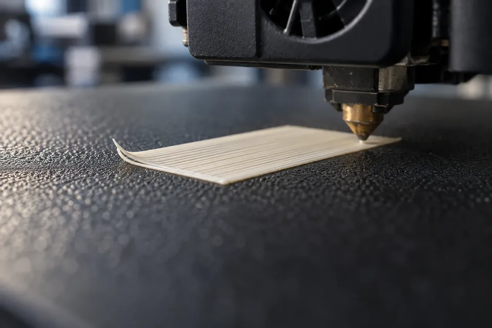
If PLA is not sticking to PEI, watch what happens during the first few passes. Separate strands, a ridged patch and a corner that rises an hour later point to different problems. Before changing temperatures or lowering the nozzle, identify which failure you actually have.
A useful first test is a small, flat patch you can stop after its first layer. Use the correct printer, nozzle, material and build-plate profile. Keep those settings recorded while you inspect the result; a string of unrelated adjustments makes the next failure harder to explain.
Does it fail immediately, or only after the base is down?
Look at the first perimeter and the lines that fill it. Does the filament land on the plate, or follow the nozzle around a turn? Do adjacent lines touch? Is a previously deposited strand dragged away by the next pass? These observations give you something more specific than “poor adhesion.”
If the initial layer stays flat and a corner curls later, set that case aside for now. Later lifting also involves the growing part, its geometry and its surroundings. A first-layer adjustment cannot be judged from a corner that moves long after the nozzle has left the base.
Stop a failed patch before loose strands gather around the nozzle. Let the machine finish its stopping routine, then remove the loose material according to its instructions. Restarting over scraps adds another variable to the test.
Confirm the plate and profile before interpreting the lines
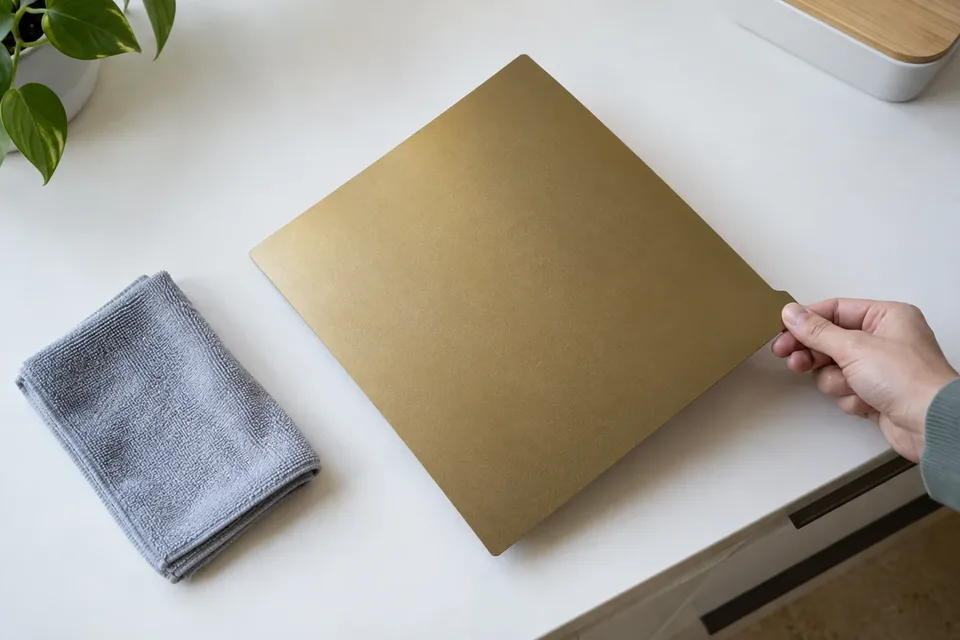
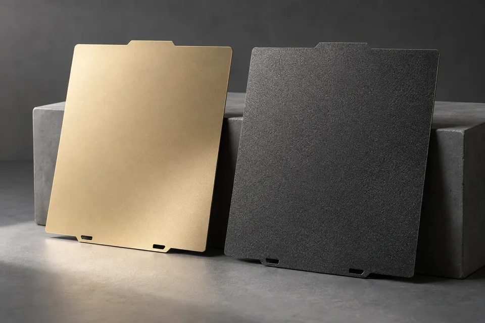
Check the exact sheet selected in the slicer or printer. “PEI” can mean a smooth film or a textured coating, and the available profiles may account for those surfaces differently. If you recently changed sheets, a successful setting from the previous sheet is not automatically the right starting point. Our smooth versus textured PEI comparison explains the surface differences.
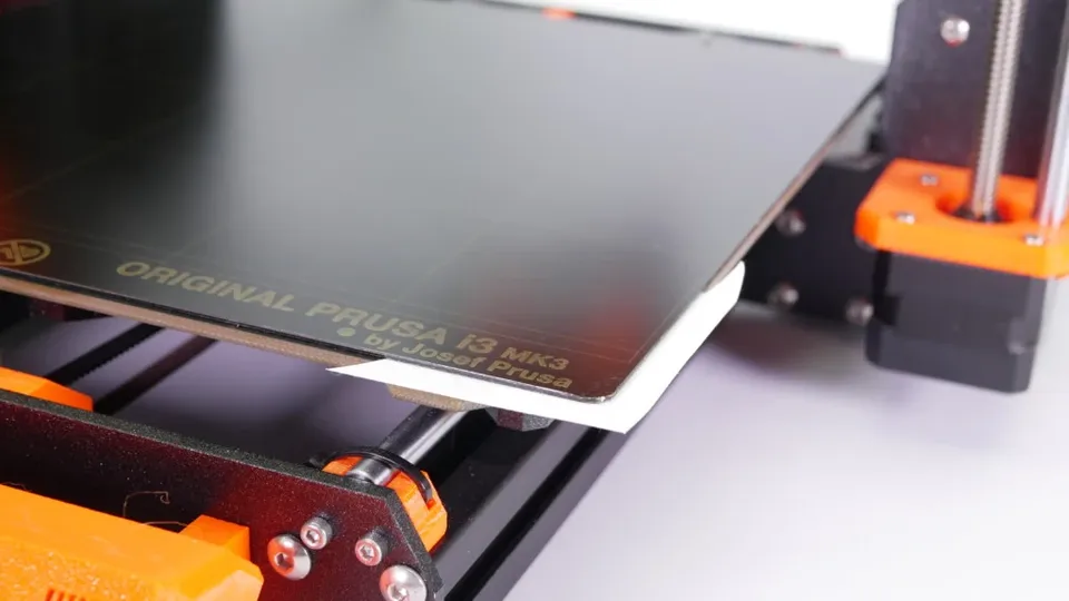
For a removable sheet, check that it lies against the bed as intended, with its locating features properly engaged. Inspect underneath for scraps. Do this with the printer stopped and at a temperature suitable for handling. A sheet resting on debris can change the local surface even when its top looks clean.
Prusa’s first-layer troubleshooting guide treats sheet positioning, calibration and print settings as separate checks. Apply the machine-specific procedure in your own manual; do not borrow another printer’s button sequence or adjustment value.
Read the patch: gaps, a continuous surface, or raised ridges
Rounded strands with spaces between them
Visible gaps mean the deposited lines are not forming a continuous base. Too much nozzle-to-surface distance is one possible explanation, but the photograph alone does not establish it. A wrong profile or inconsistent extrusion can also produce an incomplete patch. Check the selected configuration before treating every gap as a request for a lower nozzle.
Compare the lines with each other. If they are consistently separated across the patch, investigate a general setup issue. If their width changes unpredictably or the flow stops intermittently, include the extrusion path in your diagnosis rather than continuing to press the nozzle closer.
A joined patch without prominent ridges
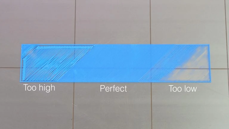
Adjacent lines should meet to form a coherent first layer. The useful comparison is between obvious open gaps, a joined surface and excessive ridging. Textured PEI leaves its own surface pattern, so a textured underside does not have to look like a smooth-sheet sample.
A rough patch that the nozzle plows through
Ridges pushed up beside the nozzle, material accumulating along its path, or a visibly over-compressed base are reasons to stop. Moving closer again is not a sensible response to a patch that already appears squeezed. Check the calibration and extrusion configuration before another attempt.
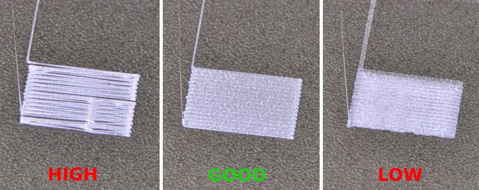
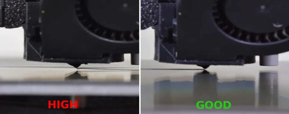
Prusa’s i3 calibration examples show the visual progression from too high through a joined layer to too low. Their Live Adjust Z procedure belongs to the covered i3 machines. Printers with other probing and calibration systems need their own procedure; some do not call for a routine manual offset adjustment.
One bad area deserves a location check
Suppose the middle of a small patch joins well, while its right edge breaks into loose lines. That result is different from uniform failure across the plate. Note the position, clean that area using the sheet maker’s method, and repeat the same patch without changing several slicer settings at once.
If appropriate for your machine, move the same short test to another area. Failure that stays at a bed location makes sheet seating, local contamination and calibration worth investigating. Failure that follows one feature of the model makes its toolpath and geometry worth a closer look. This comparison narrows the next check; it does not prove a defective bed.
Fingerprints and residue still matter even after a quick wipe. Use the existing PEI cleaning instructions for that job, then handle the sheet by its edges. Adding another cleaning product without checking compatibility can create a new problem.
Make the next print a controlled test
- Save the starting point. Record the plate, PLA profile and first-layer settings, plus the location of the failed patch.
- Correct an identified setup error first. A wrong sheet selection or trapped scrap is more actionable than a guessed temperature change.
- Use the printer’s calibration procedure if the line pattern calls for it. Avoid transferring numerical offsets between machines.
- If setup and calibration look right, change one relevant setting. Keep temperature changes within the filament and sheet guidance. Evaluate first-layer speed separately rather than changing speed, flow and heat together.
- Inspect the new first layer before committing to a long job. Check the perimeter, the filled area and a second relevant location if the earlier failure was local.
A joined patch that remains on the sheet gives you a practical baseline. Save that profile and return to the actual part. If the failure changes from immediate loose lines to later corner lifting, record that change too: you have reached a different problem, and the next adjustment should address that later stage.
Our standard: Clear sources, practical limits, and no invented test results. Read our editorial policy.
Evan Carter
Evan covers the fundamentals of desktop 3D printing, from first-time setup and calibration to common print failures and everyday maintenance.