Brim vs Mouse Ears: Choosing Where a Print Needs Grip
Compare a full brim with local mouse ears for lifting corners. Inspect OrcaSlicer previews, tune the contact gap and account for edge cleanup.

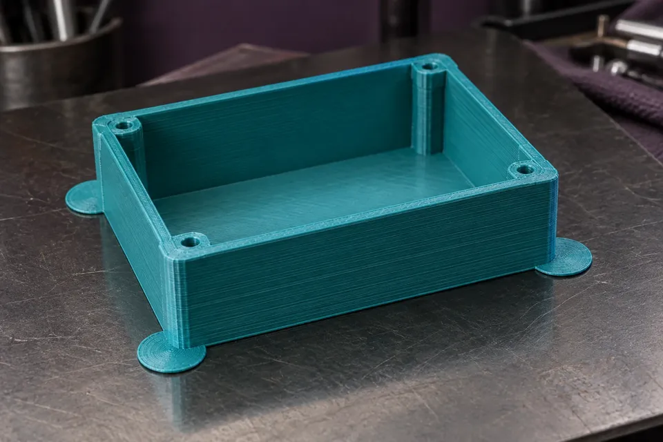
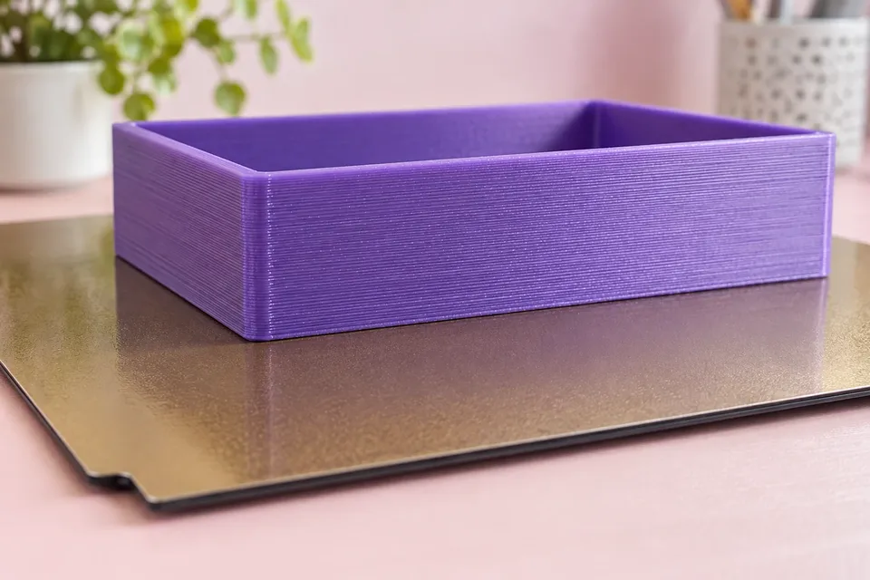
If only two corners of a rectangular print lift, adding material around every edge may be more than the part needs. Mouse ears put small brim extensions near selected corners. A full outer brim provides added contact around the outside perimeter. Choose between them by looking at where the base loses contact and what you can comfortably clean up afterward.
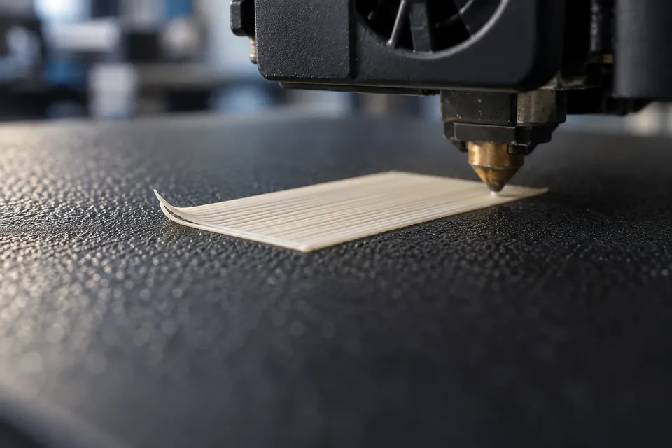
Both approaches depend on a sound first layer. When the first lines already slide or separate, work through the PLA first-layer diagnosis before comparing brim shapes. The comparison here is for a base that initially prints properly but needs more help staying flat.
Mark the lifting area before changing the slicer
Look at the failed part and locate the lifted edge. Is it a sharp outside corner, an extended side, or several areas around a small base? Keep the model orientation and printer setup recorded so you can compare the next result with this one.
A pair of small corner tabs is a reasonable trial when the problem is localized. If much of the perimeter loses contact, a continuous outer brim gives you a broader starting point. These are ways to choose a test, not a promise that either shape will overcome every cause of warping.
Also consider the finished part. A housing that mates along its bottom edge may need careful cleanup around that entire edge. A few removable corner tabs can limit the cleanup area, while a fragile corner may make a tab awkward to remove. Decide where added material is acceptable before sending the print.
Compare the same model in the first-layer preview
An outer brim follows the outside of the base. Mouse ears add local extensions at candidate corners or sharp features. The official OrcaSlicer images below compare those patterns on the same model, so the difference is the added contact rather than a change of geometry.
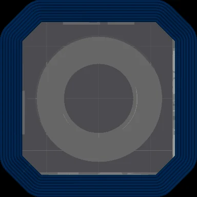
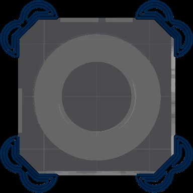
Look at the blue toolpaths relative to the gray model footprint. The full brim runs around the perimeter; the local pattern leaves more of the straight edges clear. Neither view tells you the result on your own material and plate. It tells you what the slicer intends to print.
Prusa’s skirt and brim explanation also distinguishes a brim that helps hold the object from a skirt that runs around it without the same attachment. A loop near the part is not automatically supporting it.
Set up the comparison in OrcaSlicer
The following workflow targets OrcaSlicer 2.4.2, a stable release. Use the process settings and search for “brim” if your panel layout differs. The project’s current wiki also documents newer features, so a setting shown online may not be present in this version.
- Keep the original orientation and material profile. Change the brim strategy without also rotating the model or changing first-layer temperature.
- Make an outer-brim version. Choose the outer brim type, set its width and check the first-layer preview.
- Make a Mouse Ears version. Select Mouse Ears and slice again. Inspect whether the generated ears actually reach the corners that lifted.
- Compare contact and clearance. Check the separation from the object, nearby parts and any interior features before exporting the file.
Keep the two project variants with descriptive names. If you accidentally change an unrelated setting while switching modes, restore the baseline before judging the result. The point is to learn which contact pattern helps that part.
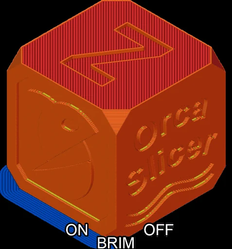
The official brim documentation covers the types and settings. Features marked for nightly builds or releases newer than 2.4.2, including the newer outer-contour-only ear option, are outside this workflow. Do not hunt for a missing control to complete these basic comparisons.
The gap matters as much as the visible shape
Brim-Object Gap is the separation between the innermost brim line and the object. Increasing it can ease removal while reducing the attachment benefit; a large enough gap leaves the added material disconnected. Check the sliced first layer rather than judging only the shape in the preparation view.
Keep the gap unchanged when comparing full brim and ears first. Otherwise a better result might come from changing the connection instead of changing the contact pattern. Once you choose a promising shape, adjust the gap separately if removal is too difficult.
There is no single gap value that deserves to be copied into every profile. The useful setting is one that provides the intended contact in the sliced toolpath and acceptable release on your material, nozzle and sheet. Evaluate that tradeoff with a short trial before an expensive long print.
Check the part after printing and after cleanup
Observe the same corner during the next job. Did it stay flat while the added material remained on the plate? Did lifting move to a neighboring section? If a local ear stays down but the adjacent edge rises, the support pattern may need broader coverage or the cause may require a different adjustment.
After normal cooling and removal, separate the sacrificial material with a method suitable for the part. Support delicate walls instead of using them as levers. Inspect the bottom edge for leftover material that could affect a mating face.
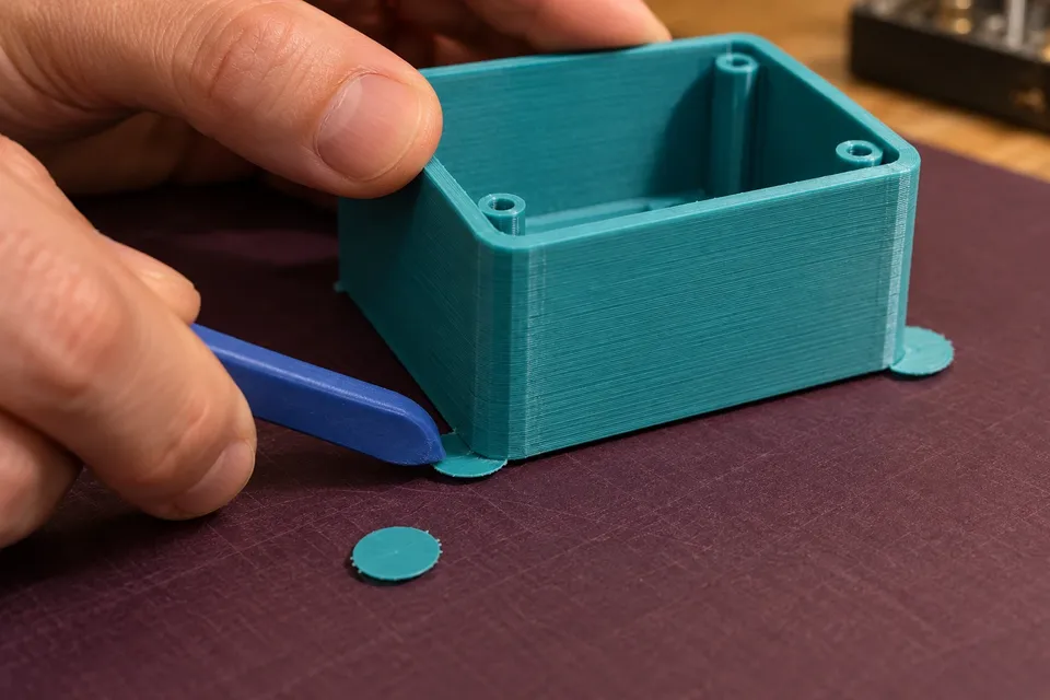
Consider both results together. A brim that holds the print but damages a functional edge during cleanup is not an ideal profile. A smaller tab that releases cleanly but leaves the corner lifted is not enough either. Keep the variant that gives the required flatness and finish, then save its settings with the model.
When more brim stops being the useful next change
If both patterns print correctly and the part still lifts, revisit the material’s thermal requirements, drafts and plate setup. Do not keep widening the brim indefinitely while changing temperatures at the same time. Look for a clear next variable based on when and where the lift occurs.
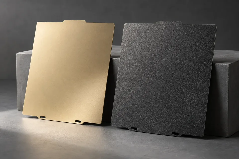
For surface selection, use the smooth and textured PEI guide. Keep that choice separate from the brim trial so you can tell what changed. A localized corner problem makes ears worth trying; a broader loss of contact makes a continuous brim worth comparing. The print and its cleanup, together, decide which approach earns a place in your saved project.
Our standard: Clear sources, practical limits, and no invented test results. Read our editorial policy.
Sophie Kim
Sophie covers slicer settings, calibration, print profiles, supports, speed tuning, and the small adjustments that turn a working printer into a consistent one.